[Date Prev][Date Next] [Thread Prev][Thread Next] [Thread Index] [Date Index] [Author Index]
Bond Graph modeling with Dia
- From: David Hoover <david hoover epfl ch>
- To: dia-list gnome org
- Subject: Bond Graph modeling with Dia
- Date: Thu, 14 Nov 2002 18:08:51 +0100
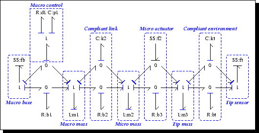
Hi,

Bond graphs are domain-independent diagrams that are used to model
mechanical, electrical, hydraulic, pneumatic, and thermal systems.  What
is particularly appealing about bond graphs is that they are modular,
allowing component interconnection, and that computer programs can
convert them to differential equations or other forms suitable for
simulation or compensator/controller design.

At the moment, the only free software that works with bond graphs is
called mtt (mtt.sourceforge.net), and it uses xfig to draw the bond
graphs.  As you can guess from the bond graph diagram that is attached,
xfig is not the best tool.  If you move a component
(R,C,I,0,1,SE,SF,SS), xfig does not move the connecting bonds (lines
with half arrows, full arrows, and flat heads).

I believe that Dia, with perhaps little modification, could be used as
an ideal tool for bond graph design.

I tried to make a custom shape with only the number '1' inside, but it
appears that text inside shapes is not displayed.  When I did this, my
shape was invisible.  Would it be easy to make the svg text get displayed?

It would be possible to place numerous anchors on the outside of the
components so that they could be connected with arrows.  The problem
with this is that if the shape is moved around, the arrows might end up
going through the center of the component.  This problem could be solved
in the following general way that could be useful for other diagrams:
The components would have a single anchor in the middle, and all bonds
(arrows/lines) would point to that single anchor.  Arrows could have a
'gap' parameter so that arrows with this parameter non-null would not
connect their end points completely, but either leave a gap between the
arrow tip and the anchor (if the gap were positive), or extend past the
anchor (if the gap were negative).  This way, all bonds would point to
the center of components, and moving components would still work correctly.

The only other change that would be necessary for basic bond graph
design would be to have an attribute that would allow one to place a
flat bar on the end of arrows, half-head arrows, and lines.  This could
be done in a general way: the line code, instead of giving a fixed
choice of different line endings as is currently done, could be written
in the following way:  Each line ending or center could have multiple
attributes that could be selected independently.  Attributes could be:
Half head, full head, flat head, half flat head, circle, triangle,
filled triangle, diamond, filled diamond, etc.  Instead of these being
mutually exclusive, they could be combined.

I was just wondering if these modifications appear to be relatively
straightforward, or not.  I think these types of enhancements could be
useful not only for bond-graph modeling, but for other diagram editing.
 What do you think?
- Follow-Ups:
- Re: Bond Graph modeling with Dia
- From: Lars Clausen
- Re: Bond Graph modeling with Dia
- From: Alan Horkan
- Re: Bond Graph modeling with Dia
- From: Dave
- Re: Bond Graph modeling with Dia
[Date Prev][Date Next] [Thread Prev][Thread Next] [Thread Index] [Date Index] [Author Index] Mail converted by Mofo Magic and the Flying D
Other Directory Sites: SeekWonder | Directory Owners Forum